
Project 4.06 Piezo as an Input
The principal behind the piezo works in both directions. So far, we’ve applied voltage to the piezo to make it vibrate. We can also make the piezo vibrate to create a voltage. In this project we read the voltage generated by the piezo when we tap it. Instead of using the microcontroller pin connected to the piezo as an output, we use it as an input.
Load the program, wait a moment, and then open the serial monitor. When you tap on the piezo hard enough so that the ADC reading is greater than 200 (it doesn’t take much!), the sketch starts a clock and then outputs the number of milliseconds after it was first tapped along with the ADC reading. The output to the serial monitor will stop when the ADC reading falls back below 200. Tap again to see another set of numbers. This gives us some idea how long the voltage spike lasts after the piezo is struck. Sometimes, there’s residual voltage on the microcontroller pin and it already reads over 200. You will see numbers streaming through the serial monitor. Try tapping the piezo to get it back near zero.
Concepts: analogRead, boolean variable type, switching pinMode
Circuits:
In the variable declarations, we use the piezo pin’s analog number instead of the digital number since we plan to use it as an input:
int piezo = A11;
We also declare a boolean variable ( a variable that can only hold the values true or false) in this sketch to start the clock when the piezo is struck:
boolean firstKnock;
In the setup() block, we set the pinMode of piezo to an input:
pinMode(piezo,INPUT);
At the top of the loop() block, we read the piezo’s voltage with an analogRead statement and load it into the variable knock:
knock = analogRead(piezo);
And reset the variable firstKnock to true:
firstKnock = true;
We found through trial-and-error that the piezo pin’s ADC reading rarely goes above 200 without it being struck. We use this threshold to detect a strike. When we detect a strike, we enter a while loop until the voltage has dissipated:
while(knock > 200){
We start the loop by lighting LED1:
digitalWrite(LED1,HIGH);
If we are just entering the while loop, we start the clock by loading millis() into the variable now. Recall that we don’t need to use the {} brackets if only one statement follows the if statement:
if(firstKnock==true) now = millis();
We set firstKnock to false so that we don’t reset the clock until we exit the loop:
firstKnock = false;
Now, we print the time elapse time in milliseconds since a strike was detected and we entered the loop. It’s followed on the same line by the value of the ADC reading which is stored in the variable knock:
Serial.print(millis()-now);
Serial.print(" ");
Serial.println(knock);
Then we remeasure the piezo to determine whether we stay in the loop or break out of it. Once we break out of it, we switch off LED1.
knock = analogRead(piezo);
}
digitalWrite(LED1,LOW);
}
Try tapping the piezo a few times and look at the output. The voltage generated by each tap can linger on the microcontroller pin. Here’s a graph created with the output to the serial monitor from a firm strike:
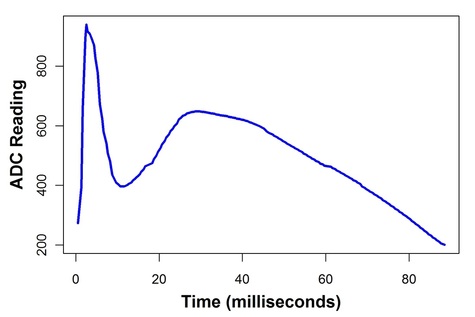
In some projects, we would like to measure the time between strikes on the piezo. We’re going to have a problem if the signal lasts up to 80 milliseconds. Let’s try to fix this problem in the next project.