
the arno board
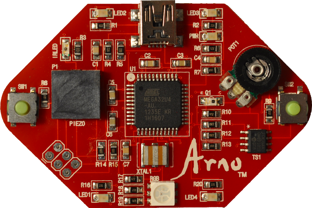
The Arno board was built so that you can learn the basics of Arduino without doing any soldering or wiring. Click on the links below to take at each of the main circuits.
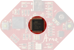
The brain of any Arduino is the microcontroller (highlighted in the picture above). A microcontroller is a miniature computer that has memory, a processor, and input and output channels all in one package. Our microcontroller is the ATmega 32U4 manufactured by the Atmel Corporation. This is the same microcontroller used on the Arduino Leonardo (or Olympia Circuit’s LeOlympia board).
The microcontroller chip looks like a bug with 44 short, metal legs. These are the microcontroller pins. The legs are soldered to the circuit board and provide electrical connections between the inside of the chip and the rest of the board. Some of the pins bring power into the chip (VCC) and provide paths to ground. Other pins are for communication through USB and with another integrated circuit on the board. The rest of the pins are input/output (I/O) pins. These pins are used to communicate with or control other components on the board. The Pin Key shows which pins are connected to each of the circuits on the Arno.
The microcontroller and the rest of the Arno board are powered by the USB hub of your computer. The USB connector on the Arno is located above the microcontroller. Your computer supplies 5V and up to 500 mA of current. That’s just right for powering the microcontroller and other components. We also load sketches and communicate between the board and computer using the USB connection. A red LED to the right of the USB connector (labeled PWR) lights up when the Arno board is powered up.
|
|
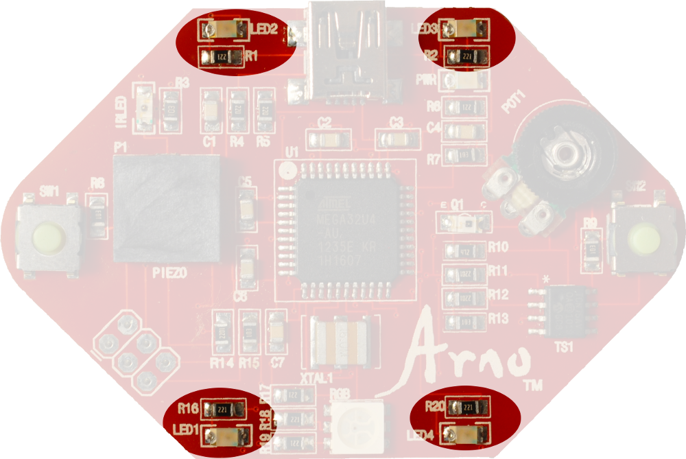
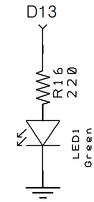
There are four single-LEDs controlled by digital pins 6 (top left of board), 7 (top right), 8 (bottom right) and 13 (bottom left). These are really four separate circuits but they all do the same thing. Each LED is controlled by programming the pin on the 32U4 chip to enter a HIGH or LOW voltage state. The LED is turned on when the pin voltage is set to HIGH, which creates a difference in electrical potential between the pin and ground. This causes current to flow through the LED. Current is limited by a 220Ω resistor in each circuit.
|
|
|
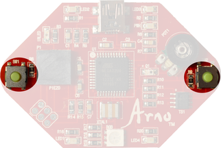
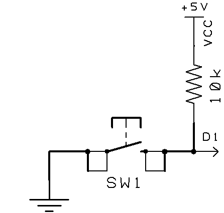
The Arno has two momentary push buttons. SW1 is on the left side of the board and is measured by digital pin 1 and SW2 is on the right and measured by pin 4. The switches are normally open. A 10K resistor acts as a “pull up” which weakly pulls each pin to 5V so that they consistently will read a digital HIGH when the switch is open. Pushing the switch moves the pin to digital LOW. We discuss highs and lows in the Programming section.
|
|
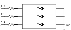
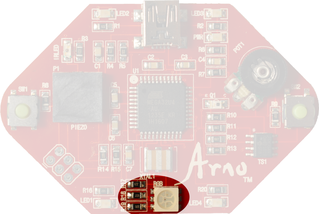
The RGB LED is simply three LEDs in a single package. The red, green, and blue LEDs are powered by digital pins 9, 10, and 11. Each of the colors can be turned on by setting the respective digital pin to HIGH. The LEDs can also be controlled by “pulse-width modulation” to make the LEDs brighten and fade (we describe pulse-width modulation in the Programming section). Combining the three LEDs in a single package allows for color blending. By varying the intensity of each LED, many different colors can be created. Current is limited by 220Ω resistors to protect the LEDs and the microcontroller. The three LEDs are tied together on the ground side.
|
|
|
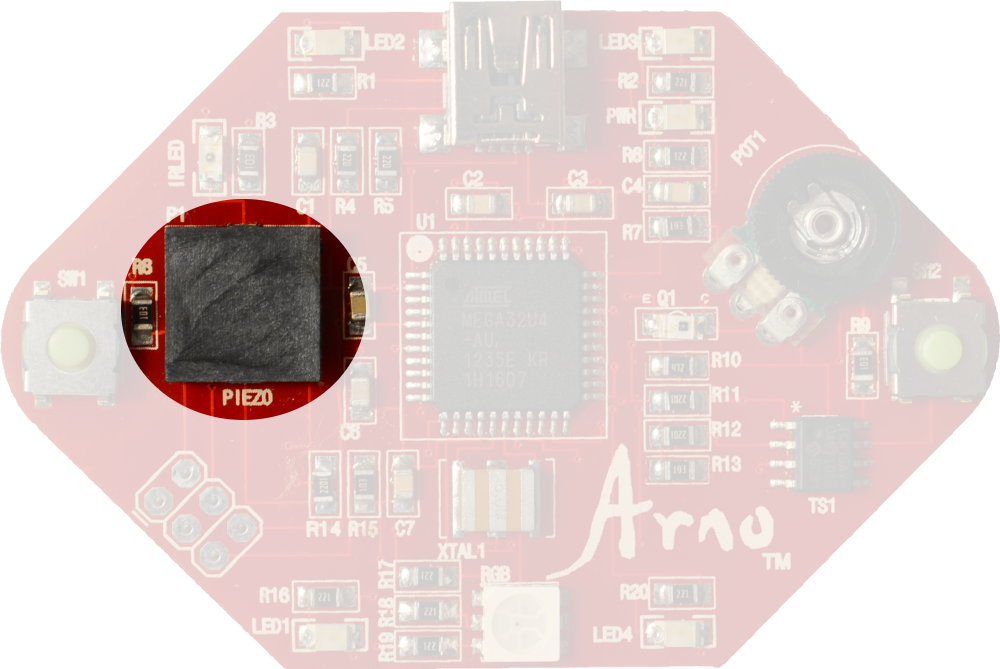
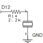
This is a simple circuit. The element is powered by digital pin 12. A 2.2k resistor limits current to protect the pin and device. The pin is rapidly switched between digital HIGH and LOW to make it vibrate and emit a tone. The pin attached to the piezo can also be used to measure voltage when it is referred to as pin A11. We will use the the Arno’s capacity to measure voltage to sense when the piezo is tapped with a finger.
|
|
|
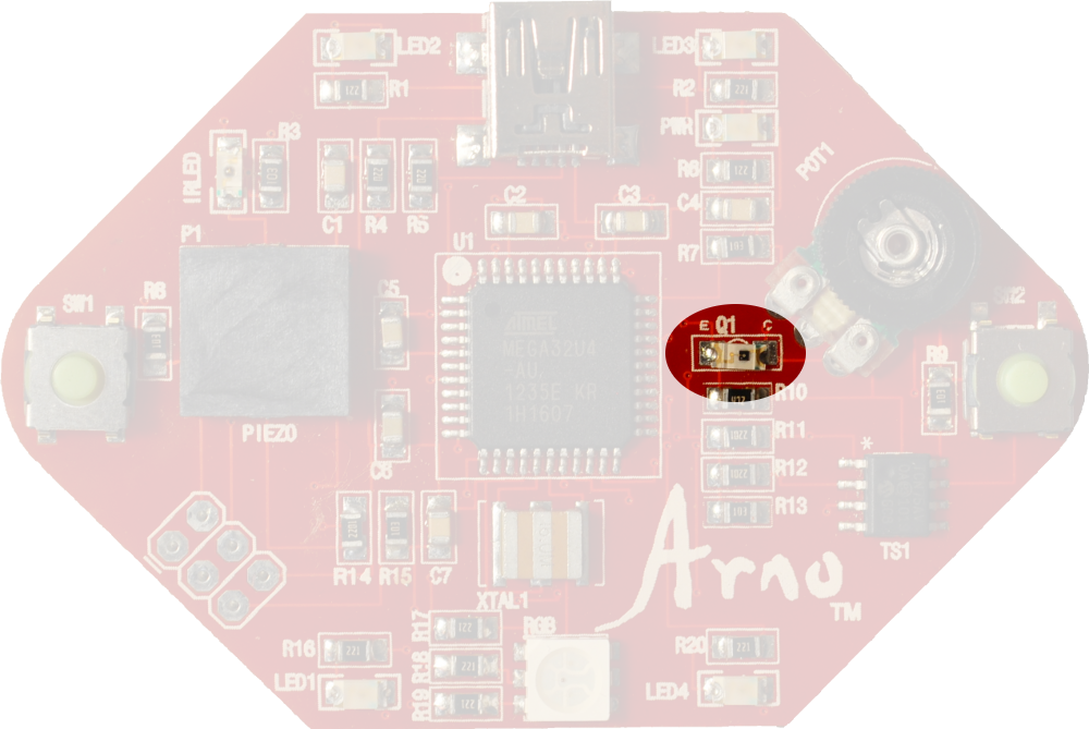
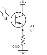
The phototransistor is measured by analog pin A1. When the phototransistor is exposed to light, the voltage drop across the the device decreases and more current flows through it. The resistor between pin A1 and ground creates a second voltage drop that is proportional to the amount of current flowing through the phototransistor. A stronger light signal creates a higher voltage reading at pin A1. The phototransistor is sensitive to infrared and visible light.
|
|

|
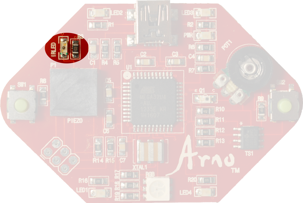
Digital pin 5 is connected to a special LED that emits light in the infrared part of the spectrum. The light is invisible to the human eye but it can be detected by a phototransistor or other devices.
|
|
|
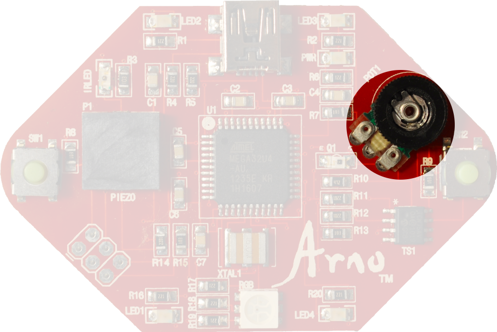
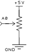
Analog pin A0 is connected to a thumbwheel potentiometer. The voltage read by A0 changes as the thumbwheel is rotated. This input can be used in a number of projects where we want to do something other than turn things on or off.
|
|
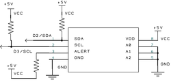
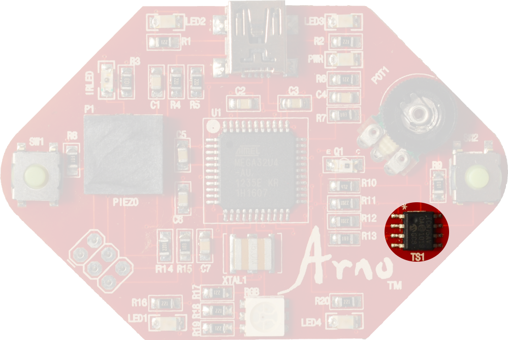
This schematic looks a lot more complicated than the others, but don’t panic. It’s actually pretty simple. The temperature sensor is a TCN75A made by Microchip Technology Inc. The sensor is powered by the same 5V VCC source as the rest of the board. It senses the temperature, converts the value into a digital format, and then passes that information back to the microcontroller.
|
The microcontroller and sensor talk in a format called I2C. You don’t need to know how to speak I2C to use it. The Arduino software has a library, called Wire, for I2C communication. There are a lot of useful devices out there that speak I2C so it’s good to learn a little bit about it. The I2C lines are at the top left of the schematic and are labeled SDA and SCL. SDA carries data. SCL is a clock so that the microcontroller knows when to expect a 1 or 0 to come through on SDA. These lines connect to digital pins 2 and 3 on the microcontroller. Both lines have pull-up resistors to keep them in a digital HIGH state until the SDA and SCL pins are pulled LOW (for a split-second) by either the microcontroller or sensor.
I2C is a “bus” communication protocol. This means that many I2C devices can be connected to the same two lines. This is great for us because we only need to use two pins from our microcontroller to talk with a lot of other devices. That leaves us with pins to do other things. The trick is deciding when it is each device’s turn to talk. Each I2C device has an address. Communication is started when the microcontroller sends out an address. If the address matches the device’s then it begins to communicate on the SDA line while the other ICs remain silent. Our temperature sensor can be setup to have different addresses depending on whether the A0, A1, and A2 pins on the IC are high or low. This is a useful feature if we want to have multiple sensors on the same board since we can set them to have different addresses. We set each of the pins low on the Arno, giving the sensor an address of 72 (the different addresses for each pin combination is set by the manufacturer). We’ll discuss how to use the TCN75A in some of our projects.
I2C is a “bus” communication protocol. This means that many I2C devices can be connected to the same two lines. This is great for us because we only need to use two pins from our microcontroller to talk with a lot of other devices. That leaves us with pins to do other things. The trick is deciding when it is each device’s turn to talk. Each I2C device has an address. Communication is started when the microcontroller sends out an address. If the address matches the device’s then it begins to communicate on the SDA line while the other ICs remain silent. Our temperature sensor can be setup to have different addresses depending on whether the A0, A1, and A2 pins on the IC are high or low. This is a useful feature if we want to have multiple sensors on the same board since we can set them to have different addresses. We set each of the pins low on the Arno, giving the sensor an address of 72 (the different addresses for each pin combination is set by the manufacturer). We’ll discuss how to use the TCN75A in some of our projects.