
Electronic Components
If you look inside a computer or another electronic device you’ll see components with different shapes, sizes, and colors arranged on a circuit board. It looks like a miniature city arranged on a green field. A circuit board is like a city – each component has a job and they are all linked together by electronic “roads” (the traces).
Electronic circuits are mapped out in schematics that show how all of the components are connected together. Each component has a special symbol. Schematics are not arranged the same way as the layout of circuit boards. That would be confusing. Instead, schematics are arranged to make it easy to see how parts are connected. You can find the schematic for the Arno board here.
Let’s take a look at some common electronic components and the jobs that they do.
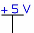
Positive supply voltage: supplies the circuit with high electrical potential. It can originate from the positive terminal of a battery or a source like a USB hub. It is sometimes also called VCC or VSS.
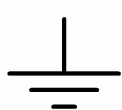
Ground: the negative supply voltage. Supplies the circuit with low electrical potential. The ground symbol is often used in circuit schematics instead of showing the connection back to the negative terminal of the battery or power supply. It is sometimes also called GND, VDD, or VEE.

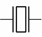
Capacitor: a device that holds a small electrical charge sort of like a tiny battery. Capacitors are often used to avoid rapid changes in voltage as different devices use different amounts of current.

Diode: a device that acts as a one-way door. Current will flow when the anode voltage (left side of the symbol) is higher than the cathode voltage (right side). Current will not flow in the reverse direction.
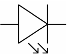
Light-Emitting Diode (LED): a one-way door that lights up when current flows through it. LEDs come in many different colors and sizes. Some LEDs emit infrared light that is invisible to the human eye but can be sensed by an infrared transistor.
Piezo Element: brings sound to our projects. The piezo element is a special material that changes shape slightly when voltage is applied. We can make it emit different tones by rapidly turning the voltage on and off at different rates. The piezo element also generates voltage when it is forced to change shape. We will use this property in some of our projects to sense a finger tapping on it.

Resistor: reduces current in a circuit (remember I = V/R). Resistors are used to control how much current will flow through different parts of a circuit. We usually want only a few milliamps of current flowing through our microcontroller and the rest of the circuit.
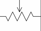
Potentiometer: a voltage divider. It’s a resistor with a “brush” that’s connected to a third terminal. The voltage of the third terminal depends on the position of the brush. Commonly used as a position sensor or in dials. You can learn more about potentiometers and other voltage dividers by looking up “voltage dividers” on Wikipedia.
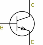
Transistor: a semiconductor that is used as a switch or an amplifier. A semiconductor is a material that acts like a good conductor in some situations and a poor conductor in others. The base of the transistor acts like a switch. A small amount of current flowing through the base allows a larger amount of current to flow between the other two terminals, the emitter and collector. We don’t use any plain transistors on the Arno (but see the phototransistor below). It’s good to be familiar with transistors, though, because they are part of many circuits.

Phototransistor: like a regular transistor but it reacts to light. Light striking the base allows current to flow between the emitter and collector.

Momentary Switch: when pressed, they either complete a circuit (a normally open switch) or “break” the circuit (a normally closed switch). The button returns to its normal position when it is released.
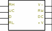
Integrated Circuit: an entire circuit in a single small package (sometimes extremely small). An IC appears as a box in a schematic with pins that connect to the main circuit. There are ICs to do many specialized tasks such as memory chips, clocks, sensors, and microcontrollers.